Documentation
Learn how to start with Automaduino!
Automaduino is a visual programming language using finite state automata for the Arduino. The goal of this project is to determine whether a language like Automaduino achieves better results compared to a interlocking block language like blockly when used in teaching. You can use the Online Editor to try it out and generate code without having to code a single line. It currently supports 15 basic components.
Installation
You can start with our Online Editor!
Automaduino will soon be available for Windows Desktop here.
What’s next?
You can start by reading about the Concepts or head over to the Getting Started guide to learn more about how to use Automaduino.
If you need more information about how the Arduino works checkout our Workshop material. There you’ll find basic instructions on how to use the Arduino and worksheets to try it out!
1 - Getting Started
Everything you need to know to get started using Automaduino!
Want to start coding using Automaduino? Great! Find out about the editor interface and what you need to do to generate code.
Overview

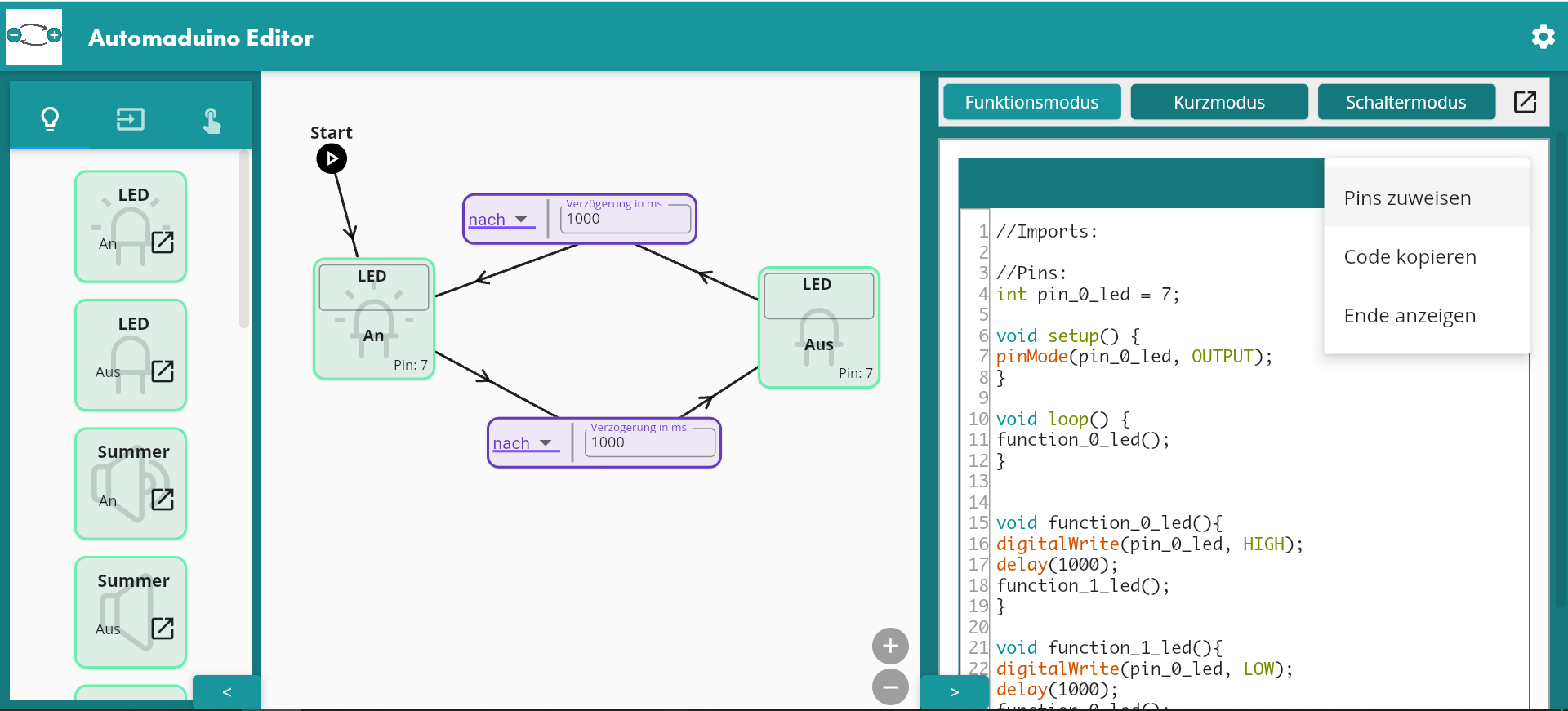
Arduino Editor Interface
The interface consists of the following parts:
- Component Drawer
- This drawers consists of all component states you can use. To find out more about the components visit the Components Page.
- Start Point
- The Start Point is the entry for your program. You need to connect it to a state for the code to be able to run.
- State
- A state consists of component and a function. The state executes the function for its assigned component. Find out more about states here.
- Transition
- A transition connects two states and determines how and when to move from one state to the next. There are multiple different transition types. Find out more about transitions here.
- Pin Assignment
- This opens the Pin Assignment dialogue. This is necessary as the Arduino needs to know to which pin your component is connected. If there is a state on the canvas that does not have a pin assigned a warning is shown.
- Code
- Here the code for the Arduino is shown! The code is automatically generated if you add a state or connect two states. It also works as a text editor if you want to change the code.
- Code Style
- The code style menu allows you to select different code styles for the generator. This for advanced programmers. All Code Styles are explained in this section.
Pin Assignment
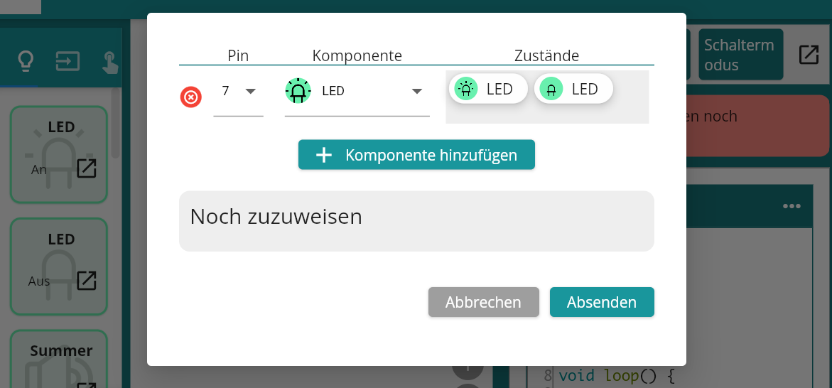
If you click on the pin assignment button a dialogue will open. Here you can assign the pins for the components on the board.
 Pin Assignment example
First add a new component, then select a pin number and a component type. If you have done this successfully you can drag a state from the list at the bottom and add it to the component.
If you’re done save your assignments by clicking on the submit button.
Tipp: You can rename your states so you know exactly which state you are assigning!
Copy Code
To use your code you have to copy it. You can always select all code in the editor by hand, but there is also a shortcut in the editor menu.
 Copy code using the editor shortcut
If your editor is closed there is a shortcut available at the bottom of the closed drawer. Next to it is also a shortcut to the pin assigment.

Copy code with a closed code editor
Arduino IDE
To upload a sketch to the Arduino you need to install the Arduino IDE.
If you’ve done this successfully, open the IDE and select your board type. The default one is “Arduino Uno”.
 Board selection Menu
Next connect your board via USB to your computer. Then select your board in the port selection. The correct port should have the board name next to it.
 Port Selection Menu
Then you can copy the code of the Automaduino editor and paste it into the Arduino editor. To upload a sketch press the upload button while your Arduino is connected. That’s it!
 Upload Button
For a full example head over to the blink page.
1.1 - Blink Example
This example teaches you how to generate the code for the blink program!
The blink program is the Hello World program for the Arduino. We use a single LED and turn it on and off again with a slight delay. As a result the LED will blink, hence the name. If done correctly we can verify that our Arduino is working correctly and the connection is working.
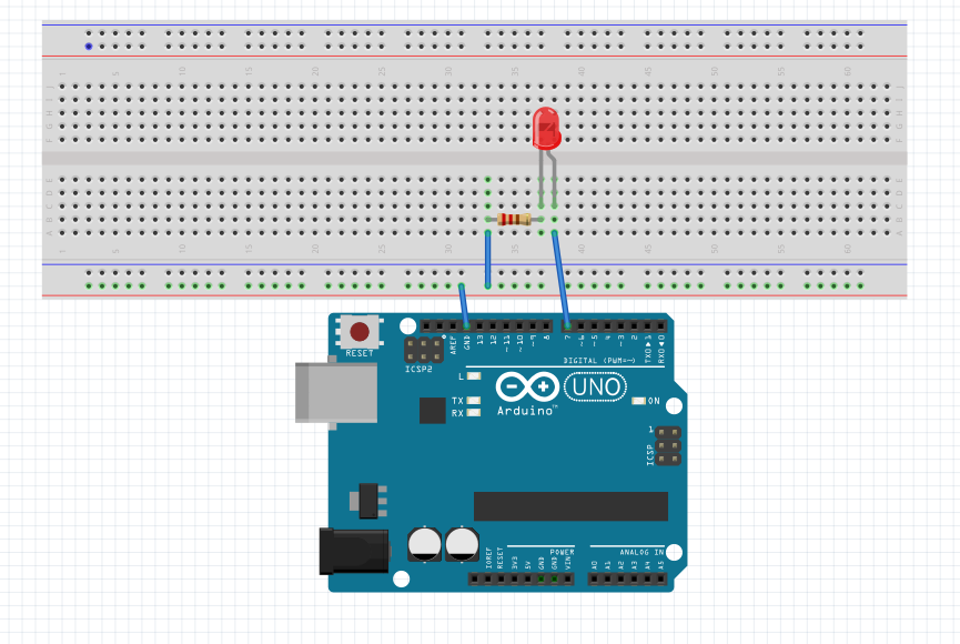
Scheme
To get started grab a LED and a resistor. Connect the LED to Pin 7 and use a breadboard to connect the GND pin with the resistor and LED.
See the scheme below on an example for the connections.
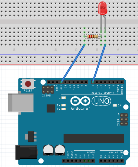
Connection scheme for the blink program
Sketch
Now we first think about how our automata should look like. Use a pen and paper and try to sketch what is happening. An example automata is shown below.
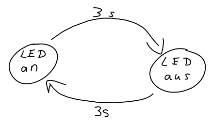
Blink sketch example
Add States
Now we’re going to translate our sketch to the Automaduino. For this we add two states to our canvas: A LED that is on and a LED that is off.
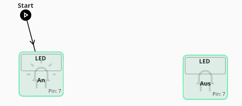
Blink states
Add Transitions
We’re now going to connect the states. We start by connecting the start point with the ON state. After we turned the LED on, we want to wait a short time and then turn it off. To do this we connect it with the OFF state and select a delay of 1000 ms. To repeat our blink we connect back to the ON state.
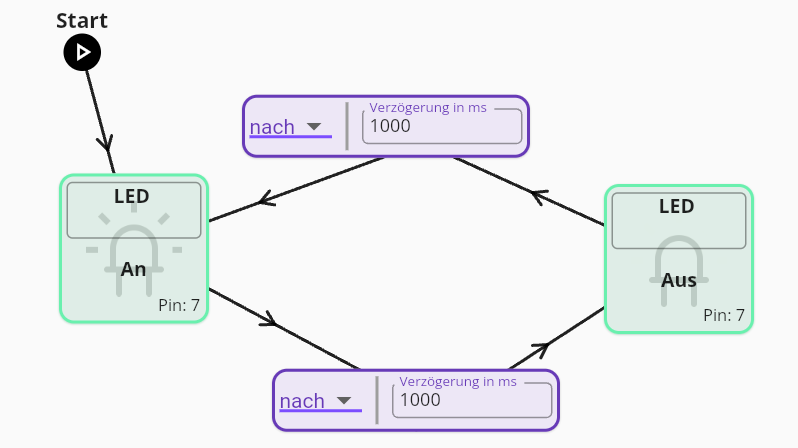
Blink transitions
Assign Pins
To finish our code generation we need to assign pins. We open the dialogue and add a LED component on pin 7. We then assign both available states to this component and submit.
Full blink example
Upload
Now copy the code into the Arduino IDE and upload the sketch as detailed in the Getting Started guide. If you connected the LED correctly it should now blink! You successfully programmed an Arduino!
Full Example
2 - Concepts
What are finite state machines and how do they relate to Automaduino?
These pages will explain to you on what concepts Automaduino was built. You do not need them to use the software, but they will give you some interesting insights.
2.1 - Automata
Automata are finite state machines and are used to represent behaviour in Automaduino.
Finite State Machine (Automaton)
A finite state machine, also called automaton, is a computation model in which a machine can at any given time hold one state. They perform a predicted sequence of actions based on a given input. States are connected by transitions. The example below is a state machine for a vending machine.

Example Highbrow CC-by-SA.
Importance in Computer Science
State machines are important in computer science. They can be used to model languages. For example parsers are often depicted as state machines.
They also have more practical uses as in UML statecharts.
Usage in Automaduino
The visual representation of Automaduino is based on state machines. Using sketches we try to determine the behaviour of our Arduino upfront and use this for our visual programming language.
Example for a sketch based on a automaton
2.2 - States
A state contains the Arduino code for a component. There can be multiple functions available for a component.
States are a key component of finite state autmata. In Automaduino they are responsible for generating the code that is executed on the Arduino.
Overview
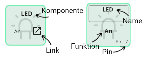
State overview
- Component
- The component this state will correspond to.
- Link
- This button can be used to open the documentation containing more information about the expected input and other features.
- Name
- This field can be used to set a specific name for this state. The name will be used in the function generation and on the pin assignment screen.
- Function
- The function executed by this state. One component can have multiple functions. They are listed below each other in the component drawer.
- Pin
- If a pin was assigned it will show the number on the state. If not the value “unassigned” will appear and the pin warning is shown in the code editor.
Highlight Option
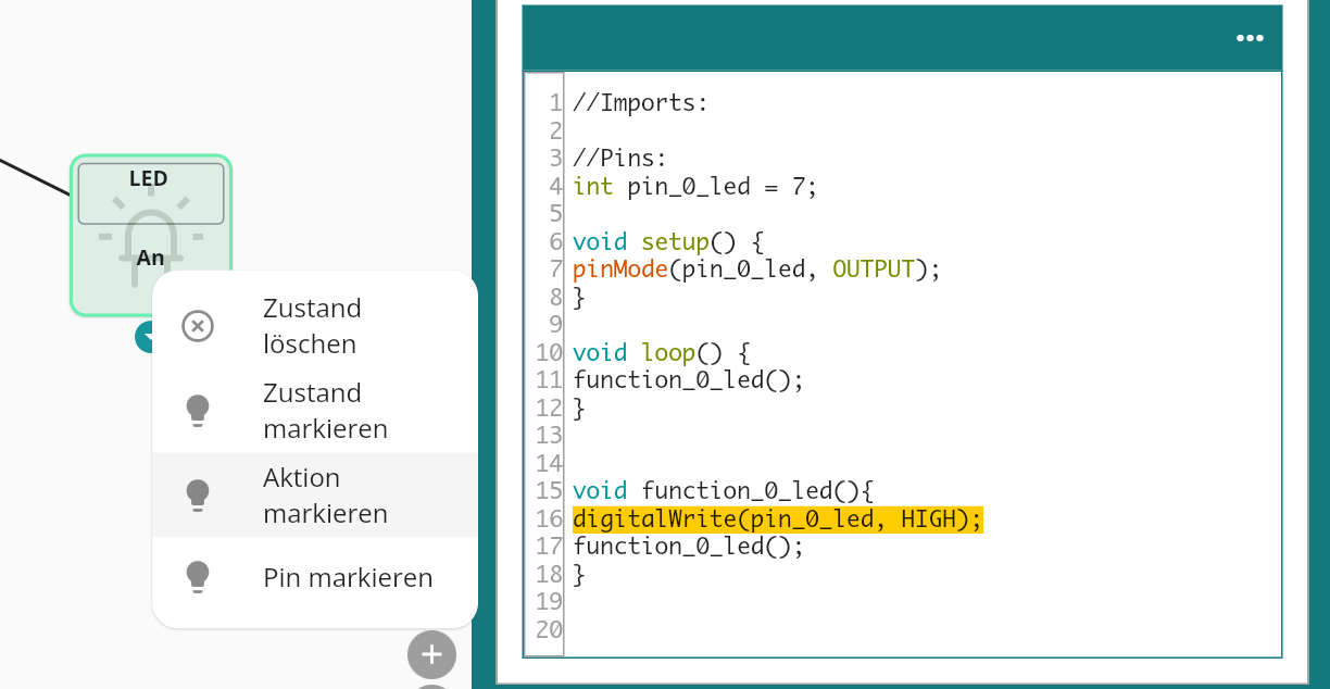
Highlight Action example
Automaduino features a highlight option to see which code corresponds to a specific state. To do this right click the block and select which part you want to see. This also works for transitions.
2.3 - Transitions
Transitions describe how to move from one state to the next. There are multiple options available.
Overview
Example of transitions in the Blink Program.
Transitions connect states. After the code in the state has been executed a transition describes how we move on to the next state. The then and delay transition are available for all types of components, while the if, ifelse and cond transitions are only available for user input and sensor components. The later three depend on the input generated by the component.
Available Transitions
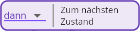
then
then example
A then transition immediatly moves on to the next state.
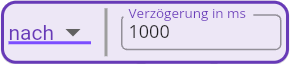
delay
delay transition example
A delay transition waits for a specified number of milliseconds before moving to the next state.
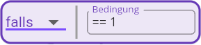
if
if transition example
An if transition will only move on to the next state if a condition is met, if not it will remain in the current state. This is useful for sensors.
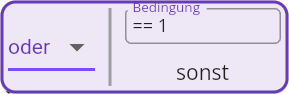
if else
If Else transition example
An if else transition will only move on to the next state if a condition is met, if not it will move on to a different state. This is useful for user input components.
cond
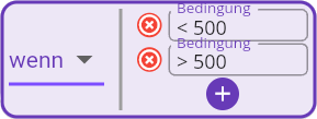
Cond transition example
A cond transition will move to different states depending on the input. This makes sense for sensors with analog output as we can define different action depending on the resulting value.
2.4 - Code Style
Code Styles are for advanced users that want to have more control how the code that is generated by Automaduino looks like.
Code Style is a feature that allows you to change how your code looks. This is not relevant for beginners, but once you want to expand on the generated code it is important to know which style you prefer. The default style the Functions mode.
Functions
The default style for the editor. This code is easy to read and to edit. It is longer compared to the abridged version tho.
- All states generate their own function based on their name.
- To move from one state to the next the function of the following state is called.
Abridged
The abridged style is the shortest available style. Here all code is generated within the loop function - This is similar to the style that is usually found in tutorials. For more complex projects this makes the code harder to understand.
- All states generate only the necessary Arduino function.
- There are no explicit transitions - The code for the following state is interlocked in the loop.
Switch
The switch version is the most true to the thought of finite state automata. Here we apply a switch machine in the loop function and set a state variable in the functions to move from one state to the next. This works as once a function execution is done, the loop function will take over again and, based on the updated state, call the corresponding function.
Compared to the other styles this execution is the cleanest, but also harder to understand for beginners than the Functions mode.
- All states generate their own function based on their name.
- A state variable is added that controls the current state of the program.
- To move from one state to the next the state variable is manipulated in the function.
- Once the code execution is done the loop function takes over and acts according to the current state.
Blink Comparison
See below how the code style affects the code generation for the Blink Example.
//Imports:

//Pins:
int pin_0_led = 7;

void setup() {
pinMode(pin_0_led, OUTPUT);
}

void loop() {
function_0_led();
}

void function_0_led(){
digitalWrite(pin_0_led, HIGH);
delay(1000);
function_1_led();
}

void function_1_led(){
digitalWrite(pin_0_led, LOW);
delay(1000);
function_0_led();
}
//Imports:

//Pins:
int pin_0_led = 7;

void setup() {
pinMode(pin_0_led, OUTPUT);
}

void loop() {
while(true){
digitalWrite(pin_0_led, HIGH);
delay(1000);
digitalWrite(pin_0_led, LOW);
}
}
//Imports:

//Pins:
int pin_0_led = 7;

int state = 0;
void setup() {
pinMode(pin_0_led, OUTPUT);
}

void loop() {
switch(state){
case 0:
function_0_led();
break;
case 1:
function_1_led();
break;
default:
break;
}
}

void function_0_led(){
digitalWrite(pin_0_led, HIGH);
delay(1000);
state = 1;
}

void function_1_led(){
digitalWrite(pin_0_led, LOW);
delay(1000);
state = 0;
}
3 - Components
What components are currently supported?
The following sections describes the available components in Automaduino. They’re grouped like in the editor into three sections: Output, User Input and Sensors.
3.1 - Output
Output components like LEDs or buzzers do not take an input but instead manipulate their environment.
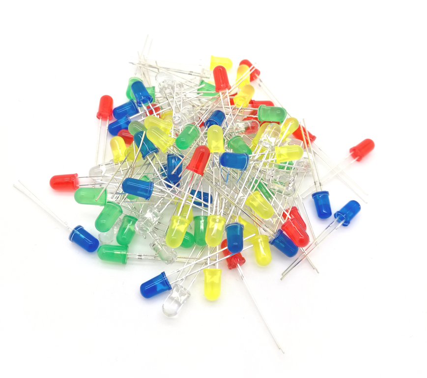
3.1.1 - LED
A LED commonly used with a resistor emits light.
Type : Output
Mode : Digital
Pins : 0-14
Tutorial : funduino
Note: Use with a resistor!
Connection scheme
Scheme made with Fritzing.
Functions
On
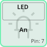
On State
Switches the component on.
void function_0_led(){
digitalWrite(pin_0_led, HIGH);
function_0_led();
}
digitalWrite(pin_0_led, HIGH);
void function_0_led(){
digitalWrite(pin_0_led, HIGH);
state = 1;
}
Off
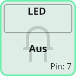
Off State
Switches the component off.
void function_0_led(){
digitalWrite(pin_0_led, LOW);
function_0_led();
}
digitalWrite(pin_0_led, LOW);
void function_0_led(){
digitalWrite(pin_0_led, LOW);
state = 1;
}
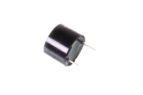
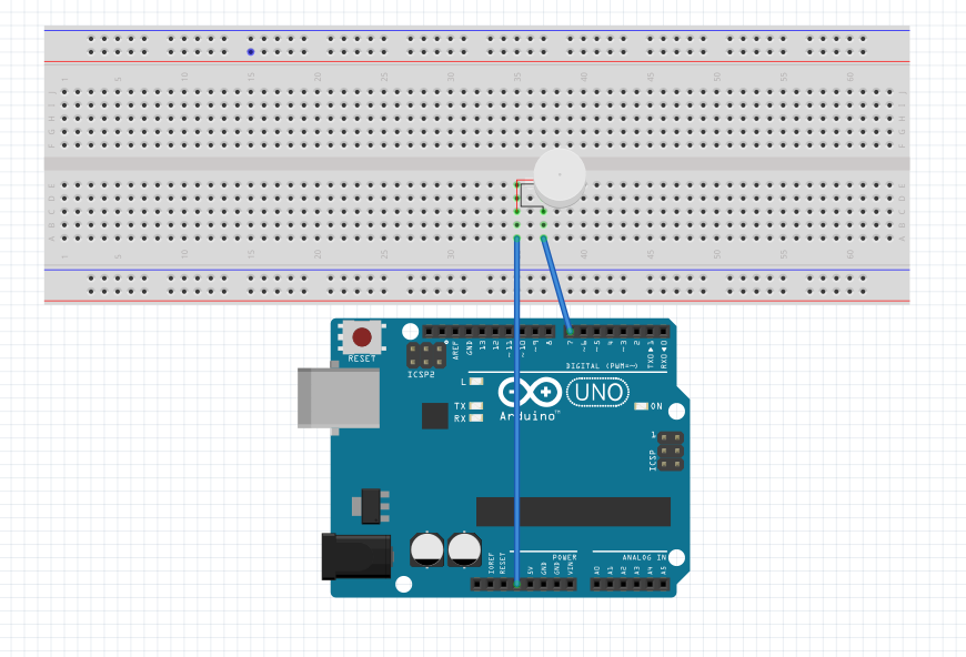
3.1.2 - Buzzer
A buzzer will emit a sound.
Type : Output
Mode : Digital
Pins : 0-14
Tutorial : funduino
Note: Use tone(buzzer, 1000) to set the tone height.
Connection scheme
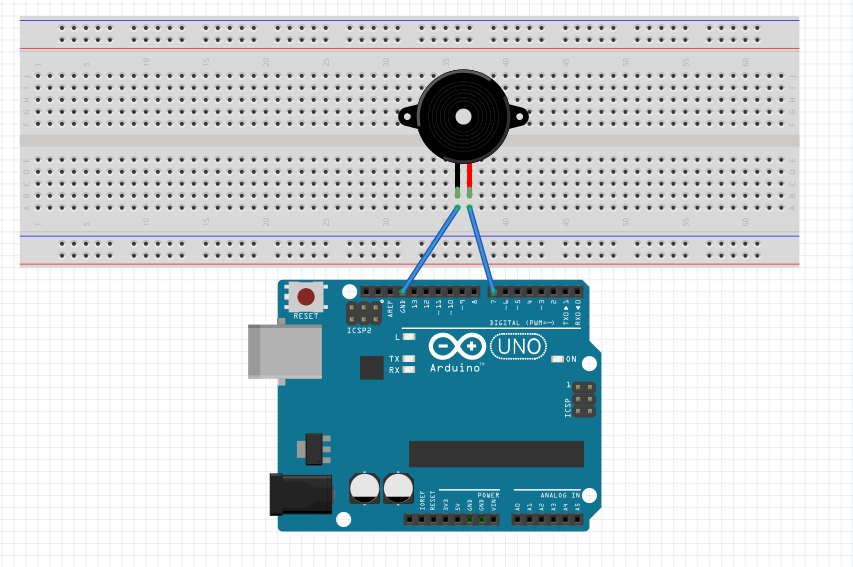
Scheme made with Fritzing.
Functions
On
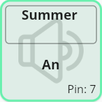
On State
Switches the component on.
void function_0_buzzer(){
digitalWrite(pin_0_buzzer, HIGH);
function_0_buzzer();
}
digitalWrite(pin_0_buzzer, HIGH);
void function_0_buzzer(){
digitalWrite(pin_0_buzzer, HIGH);
state = 1;
}
Off
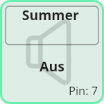
Off State
Switches the component off.
void function_0_buzzer(){
digitalWrite(pin_0_buzzer, LOW);
function_0_buzzer();
}
digitalWrite(pin_0_buzzer, LOW);
void function_0_buzzer(){
digitalWrite(pin_0_buzzer, LOW);
state = 1;
}
3.1.3 - Vibration Motor
A vibration motor will vibrate and is for example used in a smartphone.
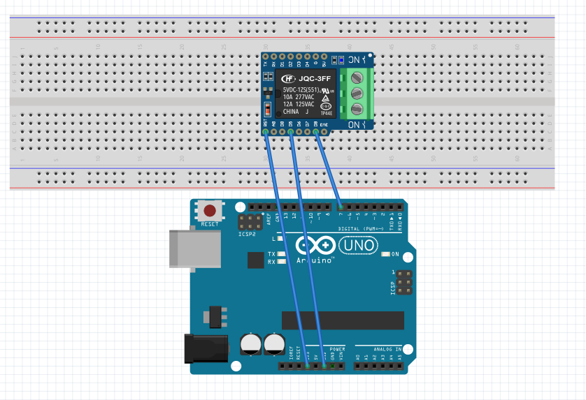
Connection scheme
Scheme made with Fritzing.
Functions
On
On State
Switches the component on.
void function_0_vibrationMotor(){
digitalWrite(pin_0_vibrationMotor, HIGH);
function_0_vibrationMotor();
}
digitalWrite(pin_0_vibrationMotor, HIGH);
void function_0_vibrationMotor(){
digitalWrite(pin_0_vibrationMotor, HIGH);
state = 1;
}
Off
Off State
Switches the component off.
void function_0_vibrationMotor(){
digitalWrite(pin_0_vibrationMotor, LOW);
function_0_vibrationMotor();
}
digitalWrite(pin_0_vibrationMotor, LOW);
void function_0_vibrationMotor(){
digitalWrite(pin_0_vibrationMotor, LOW);
state = 1;
}
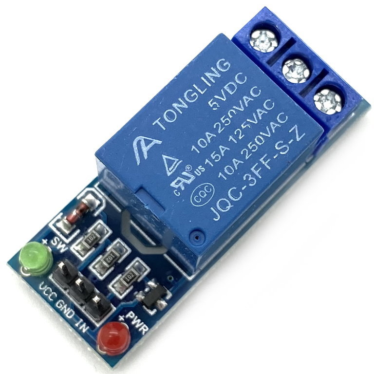
3.1.4 - Relay
A relay can be used to turn another electrical component on and off.
Type : Output
Mode : Digital
Pins : 0-14
Tutorial : funduino
Note: Be careful with external energy sources!
Connection scheme
Scheme made with Fritzing.
Functions
On
On State
Switches the component on.
void function_0_relay(){
digitalWrite(pin_0_relay, HIGH);
function_0_relay();
}
digitalWrite(pin_0_relay, HIGH);
void function_0_relay(){
digitalWrite(pin_0_relay, HIGH);
state = 1;
}
Off
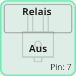
Off State
Switches the component off.
void function_0_relay(){
digitalWrite(pin_0_relay, LOW);
function_0_relay();
}
digitalWrite(pin_0_relay, LOW);
void function_0_relay(){
digitalWrite(pin_0_relay, LOW);
state = 1;
}
3.1.5 - Servo
A servo is a small motor that can be turned.
Type : Output
Mode : Servo Library
Pins : 0-14
Tutorial : funduino
Library: You need to import the servo library to use this component!
Note: Use with delay as the rotation takes some time.
Connection scheme
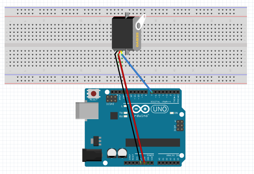
Scheme made with Fritzing.
Functions
Degree
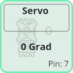
Turn servo to 0 degree
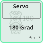
Turn servo to 180 degree
This function will turn the servo to the degree specified in the function name.
void function_1_servo(){
servo_0.write(0);
function_1_servo();
}
void function_0_servo(){
servo_0.write(0);
state = 1;
}
3.2 - Sensors
Sensors will gather input from the environment.
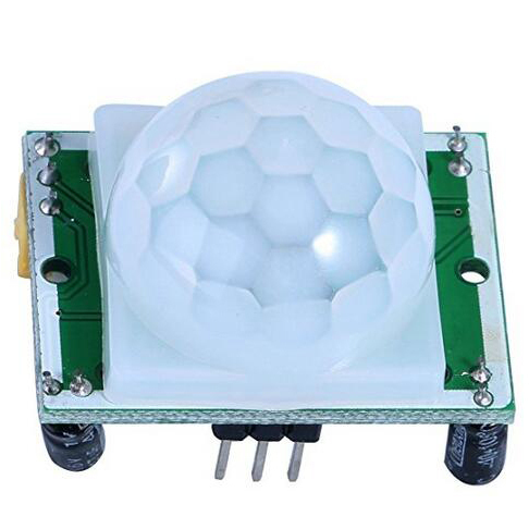
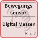
3.2.1 - Motion Sensor
A motion sensor detects motion within a certain range.
Type : Sensor
Mode : Digital
Pins : 0-14
Output Values : 0-1
Tutorial : funduino
Connection scheme
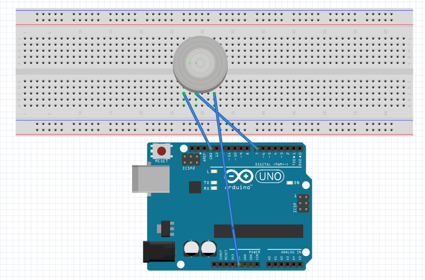
Scheme made with Fritzing.
Functions
Digital Read
Digital Read State
Reads a digital value.
void function_0_motionSensor(){
int value = digitalRead(pin_0_motionSensor);
function_0_motionSensor();
}
int value = digitalRead(pin_0_motionSensor);
void function_0_motionSensor(){
int value = digitalRead(pin_0_motionSensor);
state = 1;
}
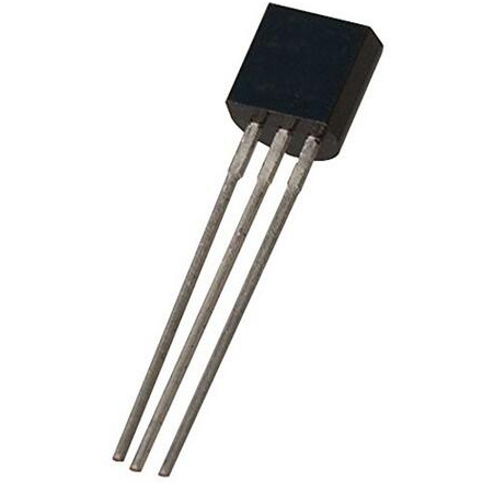
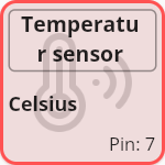
3.2.2 - Temperature Sensor
A temperature sensor measures the current temperature in the air.
Type : Sensor
Mode : Analog
Pins : 0-7 (analog)
Output Values : Value in Celsius (0-40)
Tutorial : funduino
Note: The value needs to be transformed to celsius! See code below.
Connection scheme
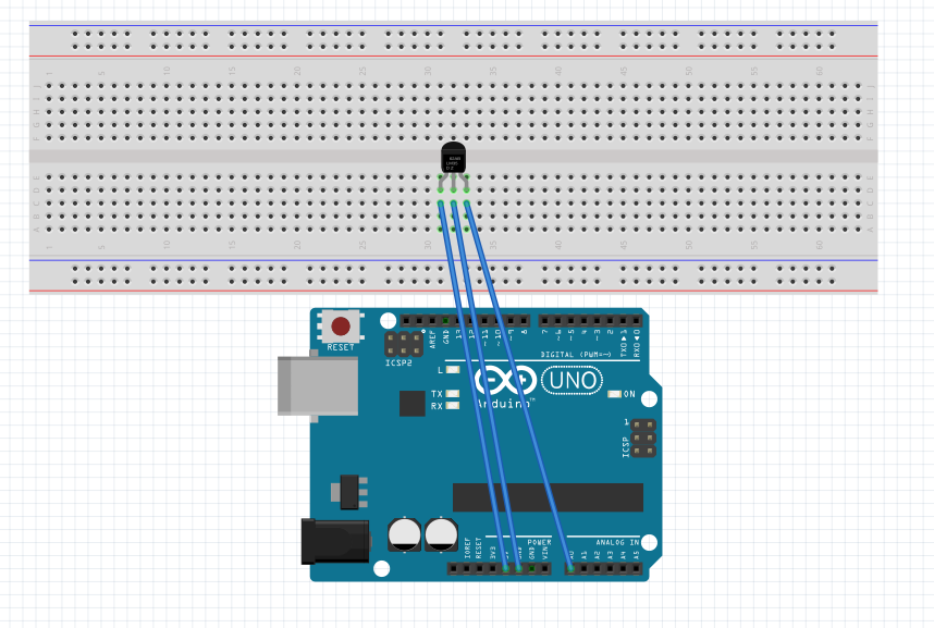
Scheme made with Fritzing.
Functions
Analog Read
Analog Read State
Reads a analog value and transforms it to Celsius.
void function_0_temperatureSensor(){
int value = map(analogRead(pin_0_temperatureSensor), 0, 410, -50, 150);
function_0_temperatureSensor();
}
int value = map(analogRead(pin_1_temperatureSensor), 0, 410, -50, 150);
void function_0_temperatureSensor(){
int value = map(analogRead(pin_1_temperatureSensor), 0, 410, -50, 150);
state = 1;
}
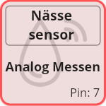
3.2.3 - Humidity Sensor
A humidity sensor measures the humidity of earth or water.
Type : Sensor
Mode : Analog
Pins : 0-7 (analog)
Output Values : 0-1023
Tutorial : funduino
Note: Only the lower parts can get wet!
Connection scheme
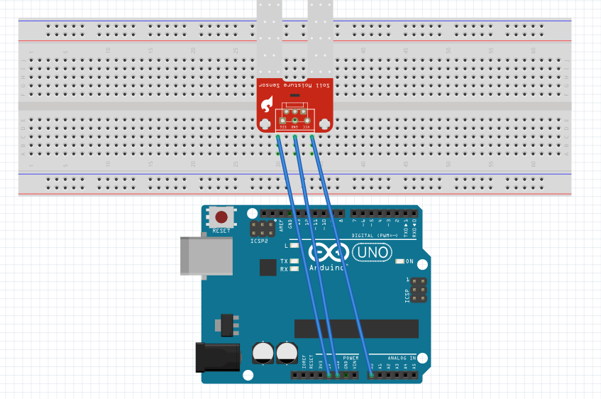
Scheme made with Fritzing.
Functions
Analog Read
Read Analog State
Reads a analog value.
void function_0_humiditySensor(){
int value = analogRead(pin_0_humiditySensor);
function_0_humiditySensor();
}
int value = analogRead(pin_0_humiditySensor);
void function_0_humiditySensor(){
int value = analogRead(pin_0_humiditySensor);
state = 1;
}
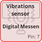
3.2.4 - Vibration Sensor
A vibration sensor detects vibration next to it.
Type : Sensor
Mode : Digital
Pins : 0-14
Output Values : 0-1
Tutorial : funduino
Connection scheme
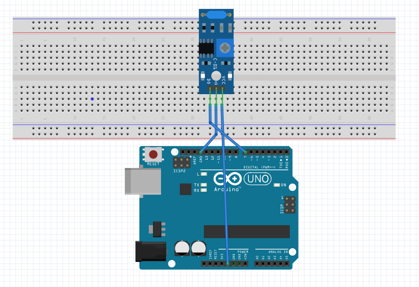
Scheme made with Fritzing.
Functions
Digital Read
Digital Read State
Reads a digital value.
void function_0_vibrationSensor(){
int value = digitalRead(pin_0_vibrationSensor);
function_0_vibrationSensor();
}
int value = digitalRead(pin_0_vibrationSensor);
void function_0_vibrationSensor(){
int value = digitalRead(pin_0_vibrationSensor);
state = 1;
}
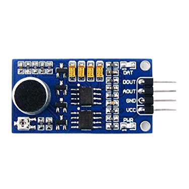
3.2.5 - Loudness Sensor
A loudness sensor measures noise.
Type : Sensor
Mode : Analog
Pins : 0-7 (analog)
Output Values : 0-1023
Tutorial : polluxlabs
Connection scheme
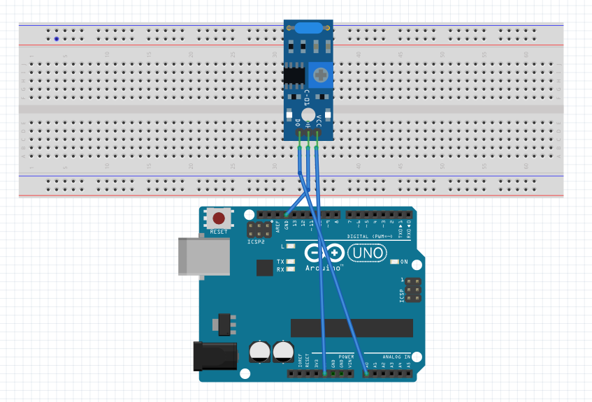
Scheme made with Fritzing.
Functions
Analog Read
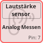
Analog Read State
Reads a analog value.
void function_0_Lautst_rke_sensor(){
int value = analogRead(pin_0_loudnessSensor);
function_0_Lautst_rke_sensor();
}
int value = analogRead(pin_0_loudnessSensor);
void function_0_Lautst_rke_sensor(){
int value = analogRead(pin_0_loudnessSensor);
state = 1;
}
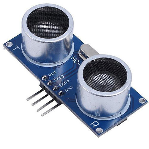
3.2.6 - Ultrasonic Ranger
A ultrasonic ranger uses a ultrasonic wave to measure a distance.
Type : Sensor
Mode : Digital
Pins : 0-14
Output Values : Distance in cm (2-300)
Tutorial : funduino
Note: To use this component use the two states to send and receive a wave!
Note: The read value needs to be transformed! See code below
Connection scheme
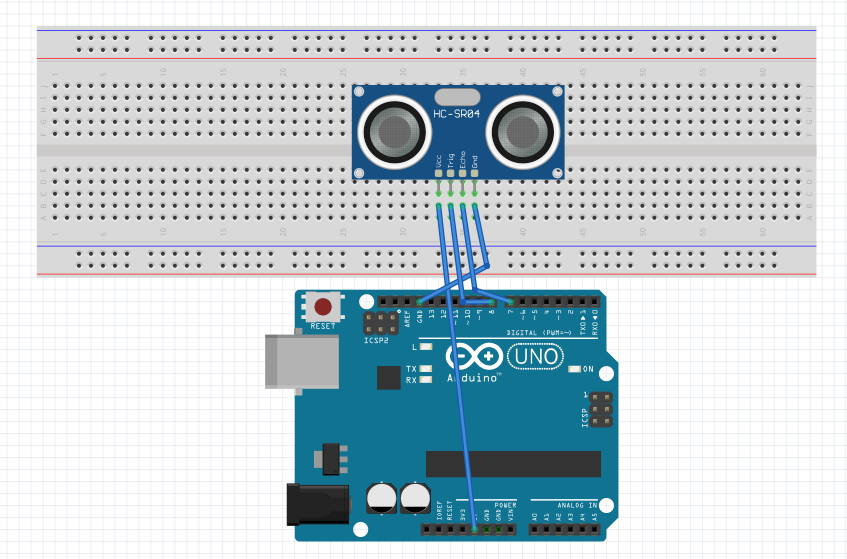
Scheme made with Fritzing.
Functions
Send Wave
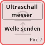
Send Wave State
Sends a ultrasonic wave.
void function_0_Ultraschall_messer(){
digitalWrite(pin_2_ultrasonicRanger, LOW);
delay(5);
digitalWrite(pin_2_ultrasonicRanger, HIGH);
delay(10);
digitalWrite(pin_2_ultrasonicRanger, LOW);
function_1_Ultraschall_messer();
}
digitalWrite(pin_2_ultrasonicRanger, LOW);
delay(5);
digitalWrite(pin_2_ultrasonicRanger, HIGH);
delay(10);
digitalWrite(pin_2_ultrasonicRanger, LOW);
void function_0_Ultraschall_messer(){
digitalWrite(pin_2_ultrasonicRanger, LOW);
delay(5);
digitalWrite(pin_2_ultrasonicRanger, HIGH);
delay(10);
digitalWrite(pin_2_ultrasonicRanger, LOW);
state = 1;
}
Receive Wave
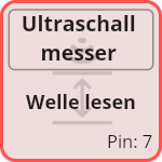
Receive Wave State
Receive a ultrasonic wave.
void function_1_Ultraschall_messer(){
long pulseValueFromWave = pulseIn(pin_2_ultrasonicRanger, HIGH);
long value = (pulseValueFromWave/2) * 0.03432;
function_1_Ultraschall_messer();
}
long pulseValueFromWave = pulseIn(pin_2_ultrasonicRanger, HIGH);
long value = (pulseValueFromWave/2) * 0.03432;
void function_1_Ultraschall_messer(){
long pulseValueFromWave = pulseIn(pin_2_ultrasonicRanger, HIGH);
long value = (pulseValueFromWave/2) * 0.03432;
state = 1;
}
3.3 - User Input
User input components will wait for a user to interact with them.
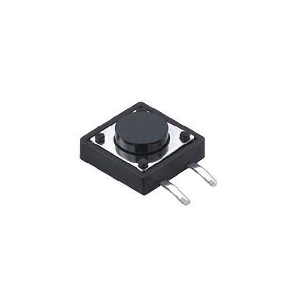
3.3.1 - Button
A button will detect if a user presses it.
Type : User Input
Mode : Digital
Pins : 0-14
Output Values : 0-1
Tutorial : funduino
Connection scheme
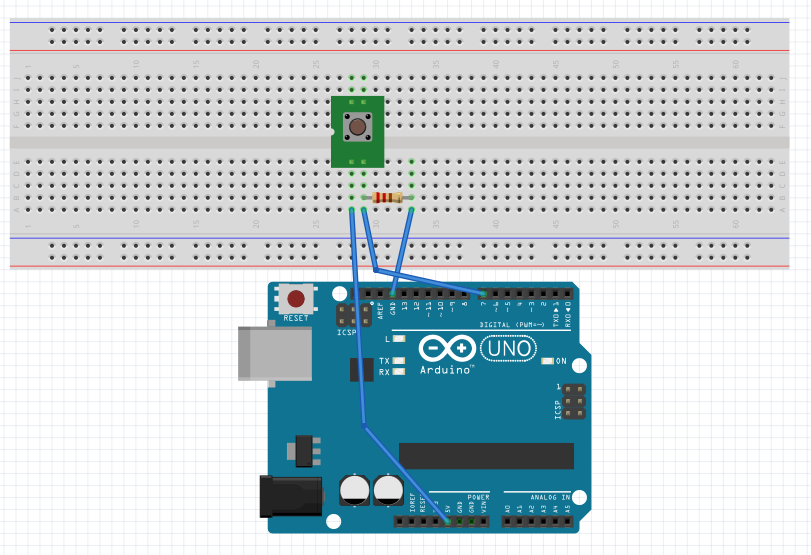
Scheme made with Fritzing.
Functions
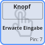
Await Input State
Awaits a digital value.
void function_0_button(){
int value = digitalRead(pin_0_button);
delay(200);
function_0_button();
}
int value = digitalRead(pin_0_button);
delay(200);
void function_0_button(){
int value = digitalRead(pin_0_button);
delay(200);
state = 1;
}
3.3.2 - Switch
A switch works similar to a button to detect an input.
Type : User Input
Mode : Digital
Pins : 0-14
Output Values : 0-1
Tutorial : funduino
Note: A switch works the same way as a button but you can always the the current status.
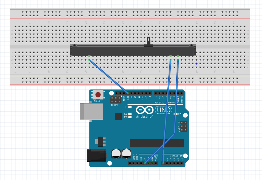
Connection scheme
Scheme made with Fritzing.
Functions
Await Input State
Awaits a digital value.
void function_0_Schalter(){
int value = digitalRead(pin_0_switch);
function_0_Schalter();
}
int value = digitalRead(pin_0_switch);
void function_0_Schalter(){
int value = digitalRead(pin_0_switch);
state = 1;
}
3.3.3 - Slider
A slider returns a value based on its position.
Type : User Input
Mode : Analog
Pins : 0-7 (analog)
Output Values : 0-1023
Tutorial : funduino
Connection scheme
Scheme made with Fritzing.
Functions
Await Input State
Awaits a analog value.
void function_0_Schieberegler(){
int value = analogRead(pin_0_slider);
function_0_Schieberegler();
}
int value = analogRead(pin_0_slider);
void function_0_Schieberegler(){
int value = analogRead(pin_0_slider);
state = 1;
}
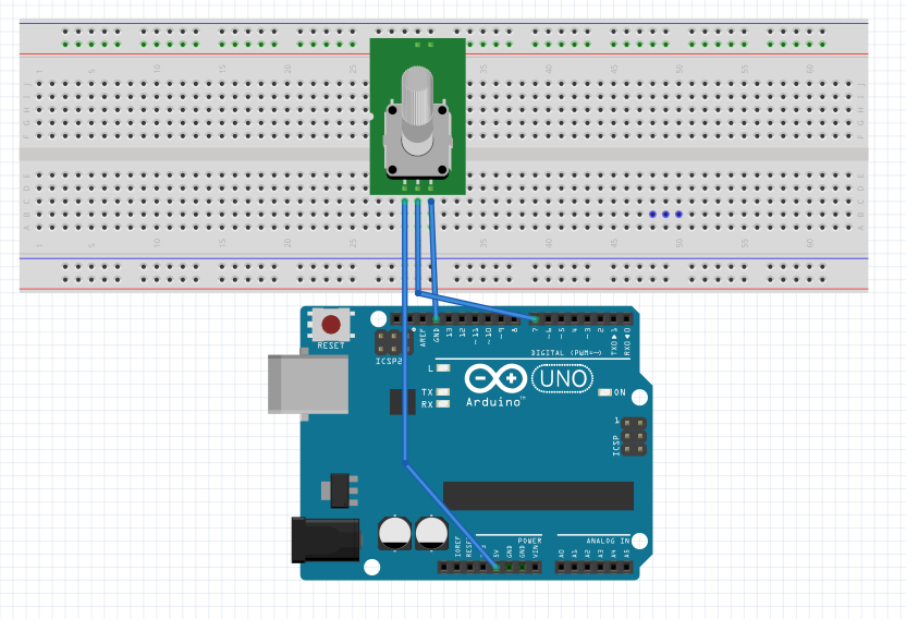
3.3.4 - Potentiometer
A potentiometer returns a dynamic value based on the rotation.
Type : User Input
Mode : Analog
Pins : 0-7 (analog)
Output Values : 0-1023
Tutorial : funduino
Connection scheme
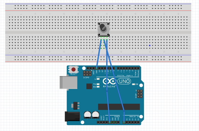
Scheme made with Fritzing.
Functions
Await Input State
Awaits a analog value.
void function_0_Potentiometer(){
int value = analogRead(pin_0_potentiometer);
function_0_Potentiometer();
}
int value = analogRead(pin_0_potentiometer);
void function_0_Potentiometer(){
int value = analogRead(pin_0_potentiometer);
state = 1;
}
4 - Workshop
Find the workshop material here.
Autmaduino was tested in a 3 day workshop in April 2022. For this I created workshop materials including presentations, work sheets and cheat sheets. The material is designed for beginners. Day 1 introduces the basic Arduino features and introduces Automaduino. Day 2 features the input and output components and introduces more complex transitions. Day 3 is about the transition to textbased programming. Finally there is a quiz to test your knowledge.
4.1 - Day One
Day one introduces students to the Arduino. We only use output components like LEDs and buzzers and explain the concept of an automata. The Cheat Sheets feature explanations on how to design and upload sketches.
Presentation
Cheat Sheets
Work Sheets
4.2 - Day Two
Day two features input components like buttons and sensors. Students will get to know concepts like if-else and conditionals.
Presentation
Cheat Sheets
Work Sheets
4.3 - Day Three
The final day will focus on the transition to textbased programming. We explain the Arduino code and try to write it by ourselves. We also show how to use tutorials to use advanced components.
Presentation
Cheat Sheets
Work Sheets
4.4 - Quiz
Test your knowledge about Arduino and programming by taking our quiz!
This quiz was designed to be answered after finishing the workshop. It features 10 question regarding the material. Can you answer them without using your cheat sheets?
Start the quiz here!