These pages will explain to you on what concepts Automaduino was built. You do not need them to use the software, but they will give you some interesting insights.
This the multi-page printable view of this section. Click here to print.
Concepts
What are finite state machines and how do they relate to Automaduino?
- 1: Automata
- 2: States
- 3: Transitions
- 4: Code Style
1 - Automata
Automata are finite state machines and are used to represent behaviour in Automaduino.
Finite State Machine (Automaton)
A finite state machine, also called automaton, is a computation model in which a machine can at any given time hold one state. They perform a predicted sequence of actions based on a given input. States are connected by transitions. The example below is a state machine for a vending machine.

Example Highbrow CC-by-SA.
Importance in Computer Science
State machines are important in computer science. They can be used to model languages. For example parsers are often depicted as state machines.
They also have more practical uses as in UML statecharts.
Usage in Automaduino
The visual representation of Automaduino is based on state machines. Using sketches we try to determine the behaviour of our Arduino upfront and use this for our visual programming language.
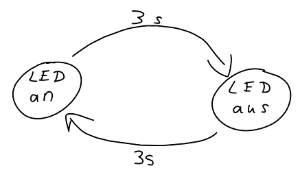
Example for a sketch based on a automaton
2 - States
A state contains the Arduino code for a component. There can be multiple functions available for a component.
States are a key component of finite state autmata. In Automaduino they are responsible for generating the code that is executed on the Arduino.
Overview
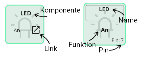
State overview
- Component
- The component this state will correspond to.
- Link
- This button can be used to open the documentation containing more information about the expected input and other features.
- Name
- This field can be used to set a specific name for this state. The name will be used in the function generation and on the pin assignment screen.
- Function
- The function executed by this state. One component can have multiple functions. They are listed below each other in the component drawer.
- Pin
- If a pin was assigned it will show the number on the state. If not the value “unassigned” will appear and the pin warning is shown in the code editor.
Highlight Option
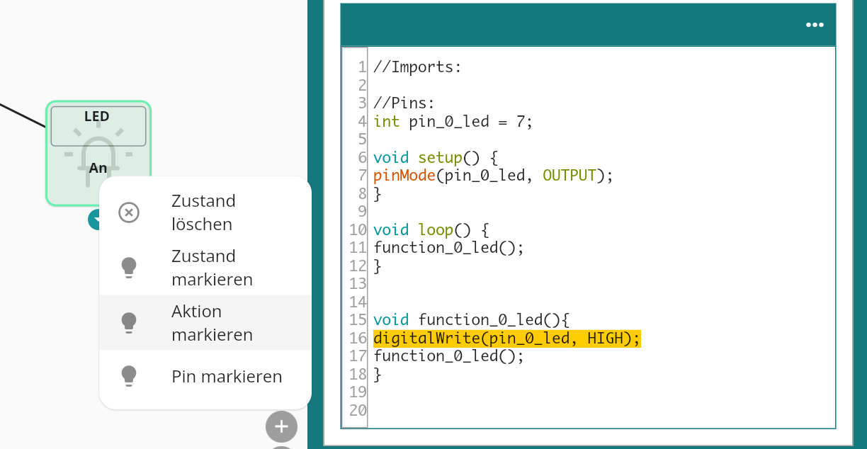
Highlight Action example
Automaduino features a highlight option to see which code corresponds to a specific state. To do this right click the block and select which part you want to see. This also works for transitions.
3 - Transitions
Transitions describe how to move from one state to the next. There are multiple options available.
Overview
![]() Example of transitions in the Blink Program.
Example of transitions in the Blink Program.
Transitions connect states. After the code in the state has been executed a transition describes how we move on to the next state. The then and delay transition are available for all types of components, while the if, ifelse and cond transitions are only available for user input and sensor components. The later three depend on the input generated by the component.
Available Transitions
then
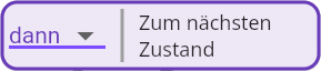
then example
A then transition immediatly moves on to the next state.
delay
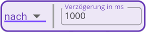
delay transition example
A delay transition waits for a specified number of milliseconds before moving to the next state.
if
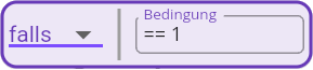
if transition example
An if transition will only move on to the next state if a condition is met, if not it will remain in the current state. This is useful for sensors.
if else
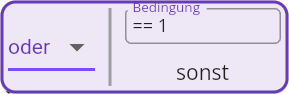
If Else transition example
An if else transition will only move on to the next state if a condition is met, if not it will move on to a different state. This is useful for user input components.
cond
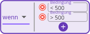
Cond transition example
A cond transition will move to different states depending on the input. This makes sense for sensors with analog output as we can define different action depending on the resulting value.
4 - Code Style
Code Styles are for advanced users that want to have more control how the code that is generated by Automaduino looks like.
Code Style is a feature that allows you to change how your code looks. This is not relevant for beginners, but once you want to expand on the generated code it is important to know which style you prefer. The default style the Functions mode.
Functions
The default style for the editor. This code is easy to read and to edit. It is longer compared to the abridged version tho.
- All states generate their own function based on their name.
- To move from one state to the next the function of the following state is called.
Abridged
The abridged style is the shortest available style. Here all code is generated within the loop function - This is similar to the style that is usually found in tutorials. For more complex projects this makes the code harder to understand.
- All states generate only the necessary Arduino function.
- There are no explicit transitions - The code for the following state is interlocked in the loop.
Switch
The switch version is the most true to the thought of finite state automata. Here we apply a switch machine in the loop function and set a state variable in the functions to move from one state to the next. This works as once a function execution is done, the loop function will take over again and, based on the updated state, call the corresponding function. Compared to the other styles this execution is the cleanest, but also harder to understand for beginners than the Functions mode.
- All states generate their own function based on their name.
- A state variable is added that controls the current state of the program.
- To move from one state to the next the state variable is manipulated in the function.
- Once the code execution is done the loop function takes over and acts according to the current state.
Blink Comparison
See below how the code style affects the code generation for the Blink Example.
//Imports:

//Pins:
int pin_0_led = 7;

void setup() {
pinMode(pin_0_led, OUTPUT);
}

void loop() {
function_0_led();
}

void function_0_led(){
digitalWrite(pin_0_led, HIGH);
delay(1000);
function_1_led();
}

void function_1_led(){
digitalWrite(pin_0_led, LOW);
delay(1000);
function_0_led();
}
//Imports:

//Pins:
int pin_0_led = 7;

void setup() {
pinMode(pin_0_led, OUTPUT);
}

void loop() {
while(true){
digitalWrite(pin_0_led, HIGH);
delay(1000);
digitalWrite(pin_0_led, LOW);
}
}
//Imports:

//Pins:
int pin_0_led = 7;

int state = 0;
void setup() {
pinMode(pin_0_led, OUTPUT);
}

void loop() {
switch(state){
case 0:
function_0_led();
break;
case 1:
function_1_led();
break;
default:
break;
}
}

void function_0_led(){
digitalWrite(pin_0_led, HIGH);
delay(1000);
state = 1;
}

void function_1_led(){
digitalWrite(pin_0_led, LOW);
delay(1000);
state = 0;
}